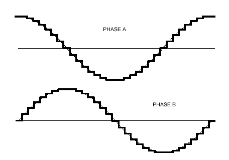
The ideal current waveform for driving a stepper motor is a Sinewave.
Two sinewaves in ‘quadrature’ (90 degrees out of phase) form the ideal current drive. If the two stepper coils follow the current waveforms depicted in diagram 1, the motor will run quietly and smoothly, the ideal condition. In fact, the “step” usually associated with stepper motors will disappear.
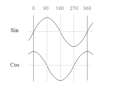
diagram 1
Let us look at why this is. The sine/cosine waves allow the motor to transition continuously from one pole (whole step position) to the next. As one coil increases in current the other decreases; the rotor advances smoothly and torque output is continuous at any given position. The torque (power) stays the same for any angle because the current is always correctly proportioned between the 2 coils. (Power is calculated as the square root of the sum of the squares of current in each coil. From trigonometry we know that sin^2 + cos^2 = 1, so the sum of the squares is constant.) The motor shaft advances smoothly during the entire cycle.
Now, let’s compare this with current waveforms of the typical Bipolar stepper driver (in Hi-Torque mode).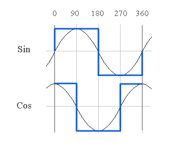
diagram 2
This is obviously not sinusoidal. There are no smooth transitions. However, this is still useful for typical stepper applications which only need to step the motor in full steps, where the motor can (to a lesser degree) hold its position without current applied, using detent magnetic torque. The stepper driver attempts quantum leaps between coil states which correspond to the motors natural full-step positions.
However, let’s look at a real-world example of a coil excited by a square wave voltage; the resultant current waveform is more like what you see in diagram 3, with current overshoot and ringing which can occur at ‘natural’ frequencies of the motor and/or mechanical system to which it is attached. This phenomenon is known as “resonance” and can be a very real problem in mechanical systems. Microstepping helps reduce resonance problems because it doesn’t allow the current levels to get ‘out of control’ like this. Clearly, the sinusoidal waveforms of diagram 1 are preferable. What type of controller can we use to control the current in the motor coils in this manner?
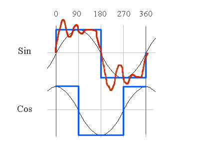
diagram 3
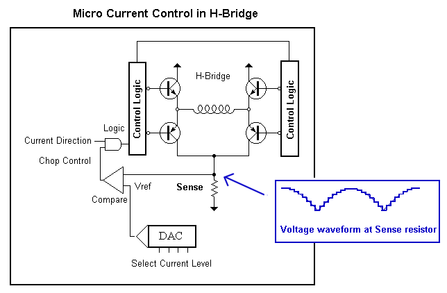
Recall the chopping current-control model from our Tutorial on Current-limiting. If we add a DAC (digital-to-analog converter) to the circuit and use it as the voltage reference, we can digitally set the reference voltage and thus regulate the current through the coil, in discrete steps. (The current in the coil is developed as a voltage across the sense resistor.) Discrete steps are not quite as good as a smooth Sinewave, but if the steps are small enough the waveform approaches a sinewave.
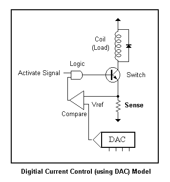
A controller that can generate fractional steps using this method of current regulation is called a Microstepping driver. A Microstepping driver can sub-divide the motors step angle into many subdivisions (4 or more) Below is a representation of the Microstepping driver (1/2 of the circuit is shown)– a chopping H-Bridge with digital current control. This circuit controls one coil of the stepper motor. An identical circuit controls the other coil, the current direction and current levels are synchronized to create the desired sine/cos quadrature waveforms. The voltage waveform at the sense resistor is a rectified sinewave (absolute value of sinewave), since current never goes negative in the sense resistor. (Recall how the H-Bridge reverses the direction of current in the coil.) It is usually convenient to look at the voltage level at the sense resistor if you want to see the current waveform.
Phasor Diagrams
Let’s now look at what current ratios are needed to produce a particular step angle. The Microstep angle can be graphically represented with a Phasor Diagram. (See diagram below) The X and Y axis indicate the current level in two respective coils A, B. A vector (ray from origin to coordinate X,Y) shows the resultant angle and Torque (magnitude of the vector) when some current is applied to both coils. Keep in mind that this diagram shows the ‘sub-angle’ between natural whole steps (poles) of the motors. On a typical 200 step per revolution motor this is 1.8 degrees. The graph below is a representation of how that angle can be further sub-divided.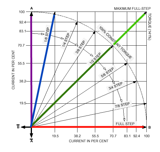 Try to locate the following Vectors and understand what it represents:
RED
Full current to coil B, only. Rotor points to a natural ‘pole’ at a whole step position.
PURPLE
Full current to coil A, only. Rotor points to a natural ‘pole’ also at a whole step position.
GREEN(LIGHT GREEN)
The green vectors are the most important to grasp. The light green vector shows what happens when you take a ‘half’ step with an ordinary (non-microstepping) controller by fully activating both coils. The angle is correct, since rotor points midway between the natural poles, but the magnitude (torque) is greater than at the whole step positions (Red and Purple vectors.) The magnitude is 1.414 times (square root of two) greater. The result is uneven torque, with resultant surges in current usage with each half step.
GREEN(DARK GREEN)
Now consider the Dark Green Vector. The angle is the same as the light green (rotor points midway between the natural poles) but the torque is now the same magnitude as the whole step positions. This was achieved by reducing the current by .707 (one half the square root of 2) in each coil. The result is even torque at the half step positions, precisely what we want.
BLUE
Now carry this concept one step further and look at the blue (1/8 step) vector. The current in the coils is precisely proportioned to achieve an eighth step between the whole step positions, with equivalent torque. You can tell that the torque is equivalent since the magnitude (length) of this ray is the same as the whole step vectors. All the microstep vectors have the same magnitude!
Once you understand the phasor diagram, you can see how the Microstepping controller uses the current levels in each of the 2 coils to achieve the desired sub-angle. What are the limits? How small a step angle can you take? This depends on the precision of the motor and the Microstep driver. Generally speaking, 1/8th to 1/16th step is a good compromise that can be achieved with ordinary motors and a good controller. Let’s look at the current ratios needed to achieve a particular 1/8 step angle.
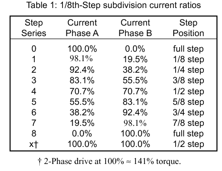
These are some pretty precise numbers. It takes a 5 bit linear DAC to get within 3% of these sinusoidal values. In order to reduce the number of control lines, some manufacturers (Allegro) use a non-linear DAC which is ‘sine-weighted’ to these percentages: 0, 19.5, 38.2, 55.5, 70.7 , 83.1, 92.4, [98.1], 100. Now all the percentages can be represented with only 3 bits. In practice, the 98.1% value is thrown out and rounded to 100% in order to fit the 9 values in 3 bits (8 values). This is a reasonable compromise.
- Current Control of Stepper Motors
- Unipolar Stepper Motor and Control
- Microstepping of Stepper Motors
- Bipolar Stepper Motor and Control
- SunPass Sign up Requirements & Sunpass Secure Login Method
- BlueStacks For Yosemite Download
- Samsung Gear Smartwatches
Current Decay – Recirculation Modes
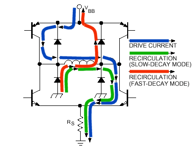
We now come to one of the most advanced topics in all of Stepper motor theory – Current Recirculation. This subject separates the men from the boys when it comes to manufacturers of Microstepping circuitry. Some choose to ignore it completely, some give you complete control. Personally, I consider Allegro’s understanding and handling of this topic to be top-notch. But first, what is Current Decay? (Note: this topic also has relevance in non-Microstepping Controllers but will not be discussed here.)
Recall that the chopping current driver turns the H-Bridge sections on and off to energize the motor coil. This is shown as the blue path in the diagram above. When the appropriate transistors are activated current flows through the coil in the desired direction (blue path). Now, when the current gets too great, (as developed across the sense resistor at the bottom) the chopping driver turns the coil off, in order to regulate the current. (BTW – All kinds of wonderful things happen when you switch coils on and off.) Where should the current go? What path should be provided for the current to decay? We need to know this in order to determine which transistors to open/close during the decay phase of current regulation. The green path provides for a slow decay, the red path allows a fast decay. Which is appropriate? That depends on on the rate that the motor is spinning and where we are in the sinusoidal curve. The objective is to follow the sinewave as close as possible. When the sinewave is at a peak, the rate of change is 0, therefore the decay should be slow, but when it crosses zero it should be faster. Depending on the frequency of the sinewave, the rate of decay could be anything! What should we do, and how will our decision effect motor performance?
In general, slow decay makes for quieter operation. But if the decay is too slow we lose Sine tracking and could run into resonance problems. When the decay is too fast, the motor is noisy and the efficiency of the chopper is decreased since it’s switching more often in order to regulate the current.
What is the solution? Allegro offers a choice of Slow, Fast, and Mixed decay modes. The percentage fast decay ratio (PFD) in ‘Mixed’ mode is even adjustable. But, this is a static solution that does not take into account motor speed. The best solution is a dynamic method, in which the decay mode tracks the current rate of change of the Sinewave. This allows the most precise tracking, and involves the least amount of “tuning” to a particular motor. It is somewhat tricky to implement, however. The decay “trajectory” must be modified each quadrant, and must actually be inverted depending on which direction the motor is spinning! (I call this method ‘Dynamic’ in my Microstepping Controllers.) But that is enough of stepper theory for now. If you followed me thus far, you can probably get a job at Allegro!
This is the end of the Current Control Tutorial. At this time, please refer to the documentation that accompanies your particular project for precautions and further information.